The Need for Flight Simulation
From a report by Hayne Constant C.B.E., F.R.S. - Director, National Gas Turbine EstablishmentThe use of flying testbeds to get early flight experience on power plants will be far more restricted than in the past. It has always been difficult to obtain for this purpose fully developed aircraft which are capable of covering the full range of speed and height over which it is desired to test the engines. As the speed of flight is raised into the high supersonic range this difficulty becomes increasingly great.
Another more insidious change has been developing over the years as a result of the wider range of conditions which the engine has been required to cope with. Not so many years ago an engine had to operate from sea-level static conditions to about 350 m.p.h. and 40,000 ft. altitude. We are now looking to the time when it must fly up to 2,000 m.p.h. and, say, to 100,000 ft. altitude. The corrections that have to be made to the sea level static performance of the engine in order to deduce its performance at full speed and maximum height will therefore be far greater than formerly. These corrections will, moreover, have to be made with little help from flying testbeds.
This wider range of operating conditions means that the power plant has to be made far more flexible in operation than has hitherto been necessary. It is for this reason that the variable intakes and exhausts, to which reference has already been made, are required. These variable features in the power plant again make it more difficult to predict flight performance from a knowledge of the performance of the components and of the complete engine under sea-level static conditions.
Probably the most important change in conditions is bound up with the interaction of the engine and its intake under non-steady conditions. In subsonic flight there are a few serious problems associated with the dynamic behaviour of the intake-engine combination, such as the consequences of a boundary-layer break-away in the intake due to disturbances caused by aircraft manoeuvres or by gun firing. In supersonic flight, however, the flow pattern in the intake is far more sensitive to disturbances, and movements of the shock-wave system may give rise to flow instabilities which have a serious reaction on the performance of the engine and hence on that of the power plant as a whole. For example, if the pilot suddenly moved his throttle position in supersonic flight, the resulting changes in the geometry of the intake, the intake shock pattern and the air flow into the engine might produce an unstable condition which would be incalculable and which would wreck the engine.
On top of all this, engines are steadily becoming more refined and therefore more temperamental and unpredictable. We can therefore no longer rely for our knowledge on how an engine behaves in flight on component tests on complete engines supplemented by a certain amount of testing in flying testbeds. It has become necessary for us to subject the power plant to conditions simulating those experienced in full flight.
Cells One and Two
From a report by P.R. Probert M.A.The first two cells were initially designed for ramjet testing on an existing air supply of 200 lb. per sec. at six atmospheres pressure. The air compressors were not used as exhausters mainly because of inherent operating requirements and also to avoid the high cost of suction air mains. Suction is provided by ejectors operating on the high-pressure air supply, a system which is cheap in first cost though higher in running cost, but this was not critical since ramjets do not operate for long periods. Considerable research has gone into the design of air ejectors, and the displacement capacity of the ejectors is about equal to the displacement of the air compressors driving them. It is one overwhelming advantage of air ejectors in this context that far lower operating pressures (or higher altitudes) can be used by using 6-to-1 air to drive an ejector than by using the corresponding compressors as exhausters.
Two test cells 12 ft. in diameter and about 120 ft. long lie one on each side of a control room which offers a direct view of engines on test. One cell is for ‘free-jet’ and the other for ‘connected’ testing. The air supply to the latter is measured for test purposes in the limbs of the bifurcated supply ducts provided. High pressure air may be fed to either cell, or diverted to drive the ejectors which evacuate the cells at low pressure. The ‘connected’ cell is evacuated directly by the ejectors, but the free-jet cell is evacuated through the exhaust end of the connected cell by transfer ducts. Alternatively, each cell can be opened to discharge essentially at atmospheric pressure into a silencing stack to which ejector exhausts are also returned.
Above atmospheric pressure the temperature of the air supply can be regulated with compressor after-coolers between about 50 deg. and 250 deg. C. Below atmospheric pressure, the temperature can also be regulated by bleeding in atmospheric air to mix with throttled compressor air. In either case two 1,500 kW heaters can be used for trimming the air temperature and as a temperature boost. Each cell may therefore take in air at high or low pressure at high or low pressure and exhaust to atmospheric or altitude conditions. While exhausting to atmosphere, 8ft. diameter cell vents can be opened upstream of the engine to permit induction of atmospheric air for exhaust gas cooling, but at any operating condition water is injected into the exhaust to keep the final temperature to 100 deg. C. or below. The air supply pressure to each cell is finally controlled by fast-operating butterfly valves. They can be operated together so that flow is diverted quickly from one cell to the other with controlled rate of change and with no change in main supply pressure.
Within the connected cell, air passes to the engine through a floating thrust box, really a plenum chamber from which air passes radially into the engine supply duct. This duct passes through both ends of the box and can float axially within the limits of annular diaphragm seals at each end. The float is restrained by hydraulic thrust-measuring gear. Within the free-jet cell, air is blown at the engine through fixed-geometry supersonic nozzles mounted in a yawing machine. This is an articulated duct system composed of telescopic pipes and ball joints. It moves within a frame under the control of hydraulic jacks and provides a wide range of engine incidence. A forged ring on the cell wall downstream of the yaw machine carries a bulk-head and spill diffuser gear.
The site has local water and fuel storage of 300,000 and 40,000 gallons respectively and a pumping capacity of 1,700 and 250 gallons per minute respectively. Each cell drains unevaporated water into a barometric well at a controlled level with an extraction system matching the fuel input to prevent flooding on an engine cut. A separate circuit provides engine and test-cell cooling water supplies.
The free-jet cell is equipped with a short-duration spark-discharge system for photographing shock-wave phenomena at the engine intake and each cell is matched by one instrument room for the remote photographic recording of all test results.
With the advent of the new larger air supply for turbine-engine trails, it has been possible to expand the duty of the first two cells by importing air from up to three of the new machines. This new supply at higher pressure improves the ejector exhaust capacity in both cells and can be used directly in the high-pressure supply of both cells. With these supplies the free-cell can test ramjet engines at Mach numbers up to 3 and higher without exact temperature simulation at heights up to 70,000 ft,. while the connected cell will test ramjets and turbojets up to their maximum density test conditions. It will also provide a wide range of useful range of reheat trials on turbojet engines. The greater part of turbine-engine testing cannot be accomplished in these two cells, which were first planned for less arduous objectives. The outstanding duties will therefore fall to two other cells.
Cell Three
From a report by P.R. Probert M.AThe duty of the altitude cell is to do connected testing on any engine at altitude exhaust conditions, at any inlet temperature, but with the ram air supply normally at atmospheric pressure or below. The cell is not primarily intended for high density or supersonic inlet testing.
 The layout of the cell and associated services is shown alongside. The cell itself is a steel shell 20
ft. in diameter and 80 ft. long. It lies in a deep cutting at right angles to the supply and exhaust
mains, to which it exhausts through a diffuser and cooling system. The cutting walls and
superstructure building contain a variety of the smaller services. The larger services lie outside
the cutting; the cold-air plant occupies a site between the main compressor-plant hall and the
cell, while an air heater will stand on the other side of the supply mains from the cell. A central
control and instrumentation building also stands beyond the pressure mains where it can serve both
the new test cells and in certain respects the ramjet cells also.
The layout of the cell and associated services is shown alongside. The cell itself is a steel shell 20
ft. in diameter and 80 ft. long. It lies in a deep cutting at right angles to the supply and exhaust
mains, to which it exhausts through a diffuser and cooling system. The cutting walls and
superstructure building contain a variety of the smaller services. The larger services lie outside
the cutting; the cold-air plant occupies a site between the main compressor-plant hall and the
cell, while an air heater will stand on the other side of the supply mains from the cell. A central
control and instrumentation building also stands beyond the pressure mains where it can serve both
the new test cells and in certain respects the ramjet cells also.The test cell is divided into two compartments by a bulkhead about 20 ft. along the cell. Each compartment has a 14 ft. wide removable cover or hatch for loading engines and gear into the cell. The upstream compartment serves both as the site for propeller-turbine engines on test and also as a plenum chamber in which air supply is maintained at the desired ram conditions of simulated flight. The down-stream chamber is the site of turbojet engines on test and in operation is maintained at the altitude exhaust pressure. Processed air enters the plenum chamber from an external ring main through a series of short connecting ducts and ports. In use for propeller turbine tests, the engine will be connected by shafting through the front of the shell to external dynamometers for power absorption. It will draw air directly from the plenum chamber while its exhaust will be ducted first through a sealed joint in the bulkhead and then right through the turbojet chamber to the outlet diffuser. A turbojet on test will be fed from the plenum chamber through a pipe sealed into the bulkhead and will also exhaust into the diffuser. Around the outer edge of the bulkhead is a ring of ports each leading to a valve through a short ducting. These valves will bypass air around the engine from the plenum chamber to the exhaust system; they can be used to maintain constant plant airflow and constant pressures in the plant system when engine air-consumption changes rapidly during acceleration or deceleration of the engine. A regulated airbleed into the exhaust system from atmosphere is provided after the cooler and before the main valves into the exhaust mains. Its main purposes are to assist in maintaining constant exhaust line pressure and plant load when engine transients occur, and also to provide sensitive exhaust pressure regulation when the plant is near its limiting exhauster performance.
The turbojet chamber will contain a floating platform, adjustable in axial position along the cell, and engine-thrust measurements will be taken from it. Engines can then be loaded outside the cell on to individual mounting dollies and the whole assembly loaded on to the floating platform. The engine air-supply ducting must contain a slip joint to permit expansion and accurate thrust measurement.
Cell Four
From a report by P.R. Probert M.AThe purpose of the fourth cell is to run engines with intakes in supersonic air streams of varying speed and density with the greatest possible freedom and safety in engine handling, incidence, rate of change of flight speed etc.
The size and duty of a complex installation of this kind depend upon the efficiency of the test techniques and the resources available. Unless the combined effect of the two main factors is such as to yield a certain critical test capacity, the system might not be worth building at all on the scale they define. The present system is expected to perform extensive, but not exhaustive, tests on the larger sizes of supersonic turbojet over the speed range in which they are expected to be the main propulsion plant of aircraft. Smaller engines can be tested over a little wider range. Had the available skills and resources yielded some 20 per cent or so less in result it would not have been possible to test actual service engines in development, and a small installation to test model engines of functional size for research purposes would then have been the only really useful level of test capacity. A great effort has been made to find techniques yielding this critical level of utility below which a large system would really be a white elephant.
Six compressor sets with all units in parallel operate in a form of closed circuit. They supply air to a variable Mach number nozzle which directs an air jet at at the engine intake. Air absorbed by the engine is kept separate after discharge from the engine, and after cooling is exhausted by the remaining two compressor sets. All the spill air is diffused in two ducts built around the engine, then cooled in two ‘spill coolers’. Enough atmospheric air is sucked in at the compressor inlets to make up the air lost by engine consumption and the whole circuit flow is then pumped back to the nozzle. This is the basic system.
The spill coolers reduce the compressor inlet temperature to the lowest possible value, while the main control of air temperature in the free jet is by selective use of compressor aftercoolers. Higher free-jet temperatures can be obtained by putting some air through the indirect heater associated with the third cell. To prevent condensation shocks in the free jet, the air in the circuit must be dry. The make-up air to the compressor is therefore dried before entry.
 The closed circuit has the great advantage that the pressure level (or effective altitude) can be
changed without change in the pressure ratio and volume flow of the main compressors. The pressure
is controlled by those compressors exhausting the engine. This arrangement will always yield the
largest free-jet area the compressors can operate, and for a given engine this beneficial effect
leads to marked improvement in the aerodynamic efficiency of the spill diffusers with very important
secondary gains in the designed free-jet area. The closed circuit also minimises the cost of
air-drying equipment. In other ways the closed circuit is less favourable. Notably the limit of
single-stage pressure ratio, when taken with diffuser efficiency factors, limits the top test Mach
number. For a large engine the top speed will be about Mach 2·5, but small engines may be tested at
speeds approaching Mach 3·0. The test gear is pictured alongside.
The closed circuit has the great advantage that the pressure level (or effective altitude) can be
changed without change in the pressure ratio and volume flow of the main compressors. The pressure
is controlled by those compressors exhausting the engine. This arrangement will always yield the
largest free-jet area the compressors can operate, and for a given engine this beneficial effect
leads to marked improvement in the aerodynamic efficiency of the spill diffusers with very important
secondary gains in the designed free-jet area. The closed circuit also minimises the cost of
air-drying equipment. In other ways the closed circuit is less favourable. Notably the limit of
single-stage pressure ratio, when taken with diffuser efficiency factors, limits the top test Mach
number. For a large engine the top speed will be about Mach 2·5, but small engines may be tested at
speeds approaching Mach 3·0. The test gear is pictured alongside.The free-jet nozzle will consist of two fixed walls and two adjustable ones. The discharge area is constant with speed, and the sped at outlet is set by swinging throat blocks into positions giving appropriate required throat areas. Steel plates attached to the throat blocks and the outlet then bend into shapes which give uniform outlet-flow distribution in the free-jet. The spill diffusers also have parallel top and bottom surfaces so that the external wall of each diffuser may be jacked to give variable intake and throat area in each diffuser. Flight incidence conditions are created by swinging the whole nozzle. The free-jet nozzle is mounted within a pressure vessel which serves as a plenum chamber from which it draws air. The engine and diffusers are housed within a vessel at the true altitude pressure. A by-pass compressor, taking about 4 percent of the nozzle flow, evacuates this chamber and delivers the by-pass flow back into the diffuser outlet mains.
The maximum volume flow acceptance of the nozzle occurs at low supersonic speeds when the nozzle throat is open, and the overall pressure ratio is least. This means that the compressors are operating at a low point on their characteristic and also near their maximum volume-flow capacity. Starting at these conditions then defines the largest free-jet section area the compressors can supply. At higher Mach numbers, as the nozzle throat is closed, the volume flow required by the nozzle falls and the pressure ratio rises. The compressors must then operate at progressively higher points on their characteristic and do indeed deliver less volume flow. In general, depending upon the circumstances of the test, they deliver more air than the nozzle requires. The excess of air must by-pass both the nozzle and diffuser and is therefore blown back into the diffuser outlets. When small engines are considered and the diffuser efficiency is at its highest, the excess air is sufficient to produce a significant injector effect on the diffuser discharge air. It will therefore be blown axially at high speed into the diffuser ducts at a section of appropriate area, so reducing the overall pressure ratio across the nozzle and the diffuser. It is the improvement of diffuser efficiency allied with the injector effect which permits higher Mach numbers to be reached with small engines.
Primary control of flight speed, and of main and by-pass compressor operation, rests entirely with the nozzle throat-area setting, but the nozzle by-pass must adjust automatically to dispose of excess compressor flow, and the diffuser walls must adjust automatically to maintain the altitude pressure in the free-jet plenum chamber. Should an inadvertent setting of excessively high Mach number occur, or some considerable engine disturbance lead to poor diffuser performance, the pressure ratio demanded might exceed the compressor capability and the sets would surge. In this case the nozzle by-pass can be opened to relieve the compressors, but flow conditions to the engine will break down. It is the prime object of the control system to prevent this situation arising.
The arrangement of engine and sill diffusers illustrated is only one of many possibilities. Space is provided to substitute radically different installations should the future require it.
The foregoing report was written before construction of Cell 4 was completed.
Instrumentation
From a report by P.R. Probert M.AThe scale of the newer installations being built is so large that vital control and observation points are necessarily remote from any one central control point. Accordingly, the control station has been taken right out of the actual test installations to a situation where cheap space can be provided for a complete central control and instrument service to each new cell. Observation will therefore be provided by industrial television cameras; the altitude cell, for example, has a series of lighting and observation ports along its length and cameras can be sited where required. An engine assembly bay is provided nearby with separate space for individual manufacturers. Here engines can be built up, equipped with instruments and remote control units and mounted on tailored test frames. Ready access and handling is provided right into each cell. Within the test cell, controls, instruments etc., will be connected into central services permanently available at the cells.
 The instrumentation service presents complex and novel problems. Plant operation is expensive and actual
running time must be used as efficiently as possible. But equally the plant will provide a unique
and vital service, and when required must be capable of rapid turn-round of engines, rapid change
from one test to another, and rapid execution of any one test. Among all these needs the requirement
is common for rapid accumulation, expression and interpretation of accurate test data. Without a
service of this sort delays would occur in the conduct of tests and of planning successive tests.
For all these reasons a comprehensive service of automatic recording, computing and presentation of
test results is being set up.
The instrumentation service presents complex and novel problems. Plant operation is expensive and actual
running time must be used as efficiently as possible. But equally the plant will provide a unique
and vital service, and when required must be capable of rapid turn-round of engines, rapid change
from one test to another, and rapid execution of any one test. Among all these needs the requirement
is common for rapid accumulation, expression and interpretation of accurate test data. Without a
service of this sort delays would occur in the conduct of tests and of planning successive tests.
For all these reasons a comprehensive service of automatic recording, computing and presentation of
test results is being set up.All physical outputs from engine instruments, eg. voltage, pressure, are wired or piped into a relay room adjacent to each cell. Here the signals are converted into digits on a binary decimal scale up to 210. This information is transferred in code to the control room, sampled through a switching system and stored in memory devices. Ultimately, all data is analysed by an electronic digital computer, and the results stored or plotted graphically by automatic methods as required. Some data, however, can be selected, computed and plotted automatically for the test controller as testing proceeds. This will enable the person in control to call of fruitless tests, or investigate further at once any observed peculiarities and generally to exercise judgement over the progress of tests.
The system as a whole uses recognised methods and available commercial equipment, but specialised transducer techniques to suit the particular needs of the plant re also under development. High frequency phenomena cannot be recorded with this system and conventional analogue apparatus must be used to record them.
Fuel Storage
From a report by W.G. Fletcher M.ENG., A.M.I.MECH E.Fuel for steam raising and test use is stored in a central tank farm containing 12 tanks each of 80,000 gallons capacity. The fuel is transferred to the test area or the boiler-house day tanks through low-head pumps. It is particularly desirable where day tanks are in use to be able to drain down the tanks with the least delay in case of fire. The units used for this duty are vane-type pumps on which the eccentricity of the rotor with respect to the block can be varied, and can in fact be moved to either side of the neutral position of no delivery.
In collaboration with the manufacturers, Plenty and Son, the potentialities of this unit were developed some four years ago for N.G.T.E. use. Constant pressure regulation, irrespective of flow or end restriction, is attained automatically by controlling the eccentricity of the block. This is positioned by a hydraulic cylinder to maintain constant outlet conditions measured either at the pump or some remote point.
The block, which is held in its normal flow position by a catch, is spring loaded towards its reverse-flow position, and the catch can be remotely released to give an instant reversal of flow in case of emergency.
Water Supply and Cooling
From a report by W.G. Fletcher M.ENG., A.M.I.MECH E.Because of the restricted operation times, a typical feature of large test plants, the actual usage of water is small, and is not expected to exceed 1,000,000 gallons a day. Nevertheless, the circulated water quantities are considerable, being of the order of 8,000,000 million gallons an hour. The main cooling systems are divided between the air-compressing plant and the test area. Because of the short running hours, the economics are in favour of mechanical draught towers as opposed to natural draught towers.
The cooling tower for the G.E.C. exhauster-compressor plant consists of eight cells each passing 500,000 gallons per hour and each cell having two induced-draught fans driven by 55 h.p. motors. The structure is continuous, the ponds being separated by reinforced-concrete walls. The ponds can be drained separately for maintenance. The water flow to the troughs is valved so that the flow circuits can be similarly isolated. At times of severe frost and low cooling duty, difficulty has been experienced due to freezing, so facilities have been provided to return the water directly to the ponds., by-passing the tower completely.
Explosion Precautions
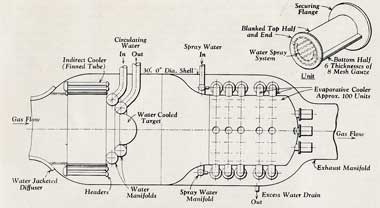
From a report by P.R. Probert M.A.In any fully enclosed combustion system there is a risk of fire and explosion. The risk is obvious here because fuel lines may break or the engine may cut while the engine itself is an unavoidable ignition source. Considerable effort has been given to these problems. Apart from the obvious precautions of preventing unnecessary fuel entering and avoiding stray ignition sources a first measure is to ensure that if an explosion
 should occur then the result should not be catastrophic. This is done partly by designing the main
steel chambers to withstand the full explosion pressure, but this does not prevent an explosion
communicating with the main exhauster plant. Explosion relief ports have been investigated, but the
rates of pressure rise in the highly turbulent conditions existing here are so fast that practicable
rates of valve opening do not lead to great relief. Water injected as a spray downstream of the
engine to drench a combustion wave passing into the exhaust system and so limit the volume within
which explosion occurs is found to be erratic and unreliable. On the other hand, various kinds of
water-cooled flame trap have given reliable results in rig trials. The preferred form consists of
layers of wire gauze wrapped into a cylinder, with radial gas flow, and sprayed with water. This
arrangement will act both as a gas cooler and a flame trap. The system chosen in this case (see
diagram) consists of a bulkhead across the cooler shell behind the indirect cooler, bearing multiple
packs of water sprayed gauze.
should occur then the result should not be catastrophic. This is done partly by designing the main
steel chambers to withstand the full explosion pressure, but this does not prevent an explosion
communicating with the main exhauster plant. Explosion relief ports have been investigated, but the
rates of pressure rise in the highly turbulent conditions existing here are so fast that practicable
rates of valve opening do not lead to great relief. Water injected as a spray downstream of the
engine to drench a combustion wave passing into the exhaust system and so limit the volume within
which explosion occurs is found to be erratic and unreliable. On the other hand, various kinds of
water-cooled flame trap have given reliable results in rig trials. The preferred form consists of
layers of wire gauze wrapped into a cylinder, with radial gas flow, and sprayed with water. This
arrangement will act both as a gas cooler and a flame trap. The system chosen in this case (see
diagram) consists of a bulkhead across the cooler shell behind the indirect cooler, bearing multiple
packs of water sprayed gauze.It would be possible to use water alone to cool the exhaust gases, but unless very large water reservoirs are available so that the sensible heat of water, rather than the latent heat of steam, is used as the heat sink, the system is uneconomical in exhauster capacity. At a given mixture temperature the water vapour fraction in equilibrium with air increases at low pressure due to the fall in boiling temperature of water. In an evaporative cooler, gases at high temperature will have a sufficient heat to raise a large fraction of steam, but if they are first cooled indirectly the steam fraction and temperature at equilibrium fall with the degree of indirect cooling employed. The present system uses a flame trap to cool by evaporating from 150 deg. C. and thereby gives a big reduction in the size and cost of the indirect cooler for only a small loss in exhauster-air capacity.
Another safety measure will also be employed. Torches have been developed to ignite flowing mixtures over a wide range of mixture strength and flow velocity. These will be installed at the exit of the diffuser. When therefore, a stream of unburned mixture, due say to an engine cut, blows into the cooler and exhaust system, it is burned off at this point and the system fills with inert products instead of an explodible gas. An engine relight will not then lead to an explosion.
Air Supply and Electrical Loads
“A meeting of the Air Supplies Committee, 24th March 1960.
“To discuss the probable air demands likely to arise during the year beginning 1st April 1960 and to decide on a suitable figure for the electrical M.D.”
Click image to expand and read…