“The control room and switch rooms are in an annexe along the side of the Compressor House, with the control room
centrally situated and overlooking the engine-room floor. The 33 kV switchgear is in two separate
rooms, one on each side of the control room. The battery room and medium voltage and 11 kV
switchgear are also in this annexe. The 33 kV switches are single busbar 600 ampére rating,
vertically-isolated oil immersed with a rupturing capacity of 750 MVA. Bus section switches divide
the sets into groups of two and are also 1,200 ampére rating. Site services are taken from an 11kV
ring main fed from a10 MVA transformer at each end.
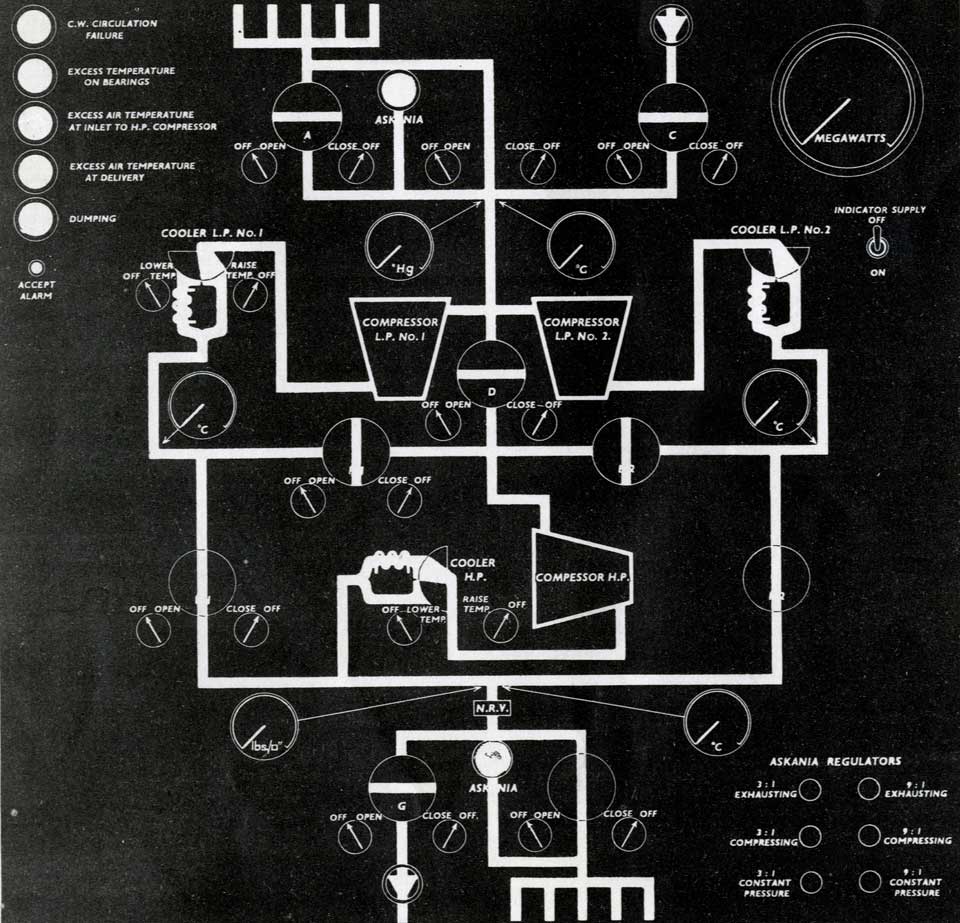
In addition to the electrical panels, the control room also contains the air desks, one to
each set, and a complete air mains diagram for the test area. The sets, having been put on to the
governor gear, are synchronised and completely controlled from this desk. Fault indications are
received here of excess bearing temperature, cooling water failure, stator temperature, etc. It is
important to maintain the air supply to the test cells, and for this reason automatic shut-down is
restricted to major mechanical or electrical faults, which have been found to be, of themselves, the
prime cause of shut-down.”
MVA=Megavolt Ampére