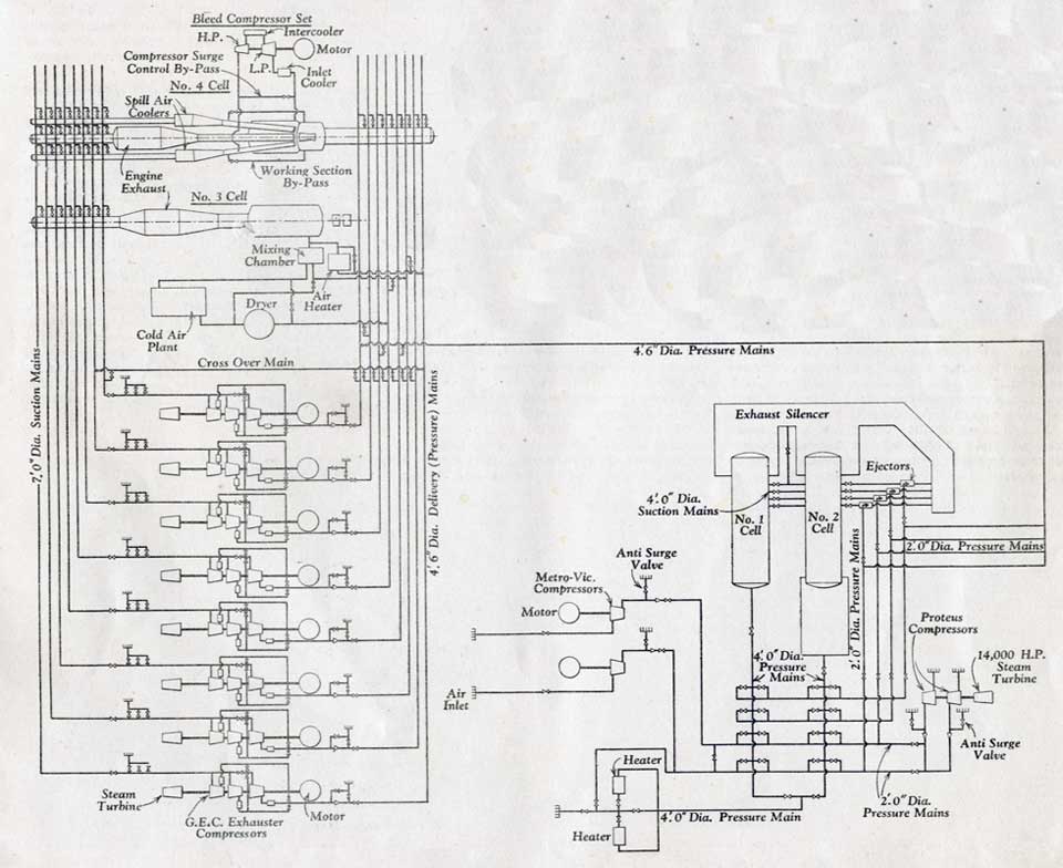
“The integrated test facility consists of the following major groupings, the disposition of which is
shown in the schematic layout.
(a) The major air supplies are from two Metropolitan-Vickers compressors, from two Bristol Proteus
compressors, and from eight General Electric Company compressors.
(b) The test cells, four in number, have the following functions:
No.1 cell. - For free-jet tests on ramjets and small jet engines throughout a range of altitudes and
forward speeds. This cell takes air from any of the three supplies singly or in combination. The
cell is evacuated by air-driven ejectors. A 3,000 kW air heater is used for preheating the air at
entry to this cell and No. 2 cell.
No. 2 cell - For connected tests on ramjets and small jet engines. air is available from the three
supplies singly or in combination. The cell is evacuated by air-driven ejectors.
No. 3 cell - For three jet or connected tests on engines of the largest type, having sea level
static air flows of up to 300 lb. per sec. This cell is equipped for icing tests and can operate
through a temperature range at inlet from -70 deg. C. to + 650 deg. C. Air is fed to this test cell
from the G.E.C. compressors.
No.4 cell - For free-jet testing of the larger engines. this cell is equipped with a variable
Mach-number blowing nozzle and flight transients can be simulated. The air supply is taken from
G.E.C. compressors.
(c) An air drying and refrigerating plant operates on an air cycle using the output of one G.E.C.
compressor. This plant feeds air into No.3 test cell at temperatures down to -70 deg. C.
(d) An oil fired air heater has an output of 36 x 106 C.H.U. per hour with a maximum delivery
temperature of 650 deg. C. This heater feeds cells 3 and 4.
The facility also includes steam boilers and a super-heater, fuel storage and transfer equipment,
and workshops and assembly bays.”